Perhaps many of you dream of assembling a music center with their own hands, but do not know where and how to start. Well, if this center can be used with both Bluetooth and WIFI or, say, as a receiver of an audio stream in a Multiroom system? And at the same time it will be able to connect to the music database on the server and manage everything via the Web interface (however, you can listen to music from a regular USB disk). If you are interested, then go ahead!
The amplifier is assembled on the TAS5713 chip, which is a class D amplifier with an output power of 25 W per channel, reproduces the range from 20 Hz to 20 kHz, with a harmonic coefficient of ~ 0.1% and an overall efficiency of 90%. It can be controlled via I2C and the sound can be transmitted via I2S.
The circuit board looks like this: 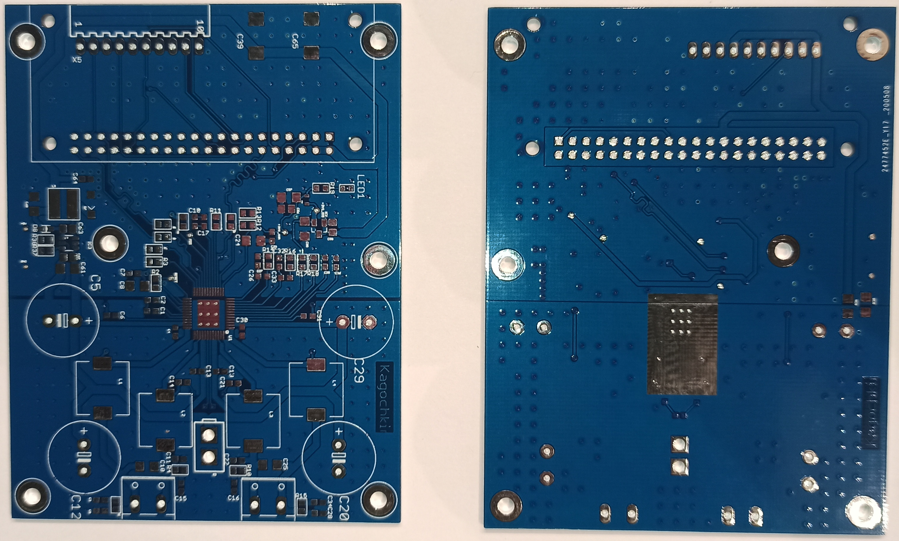 We are going to control all this using the RPI ZERO microcomputer,
 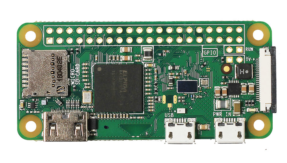 which we will also install on our board.
This is how it looks after assembly ...
which we will also install on our board.
This is how it looks after assembly ... 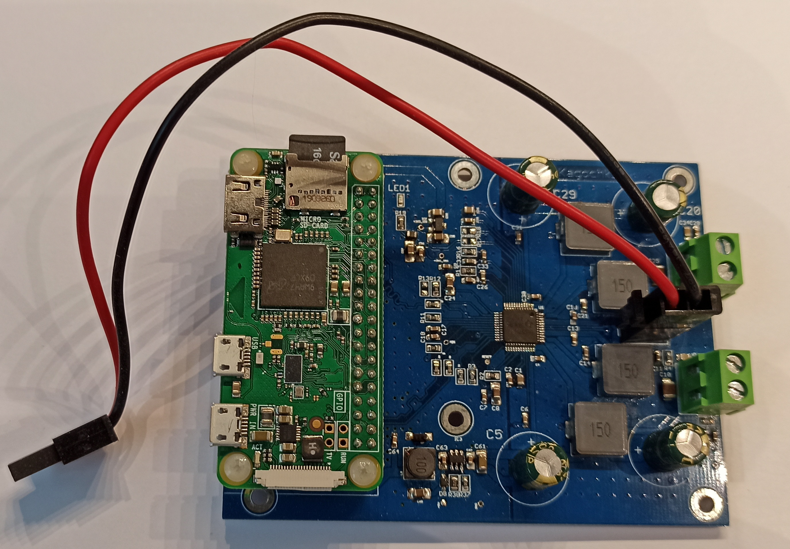
The schematic diagram can be taken here
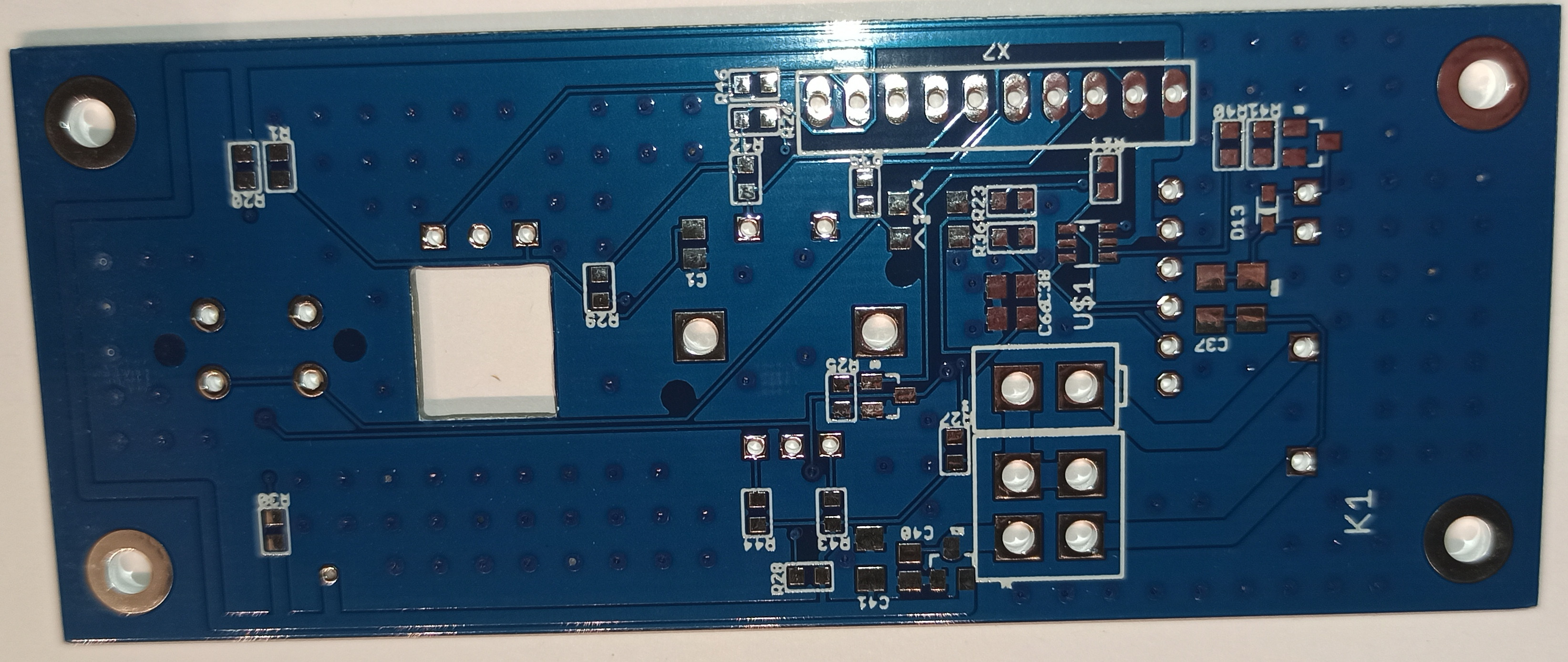
Now we need a power supply, which we will assemble on the second PCB 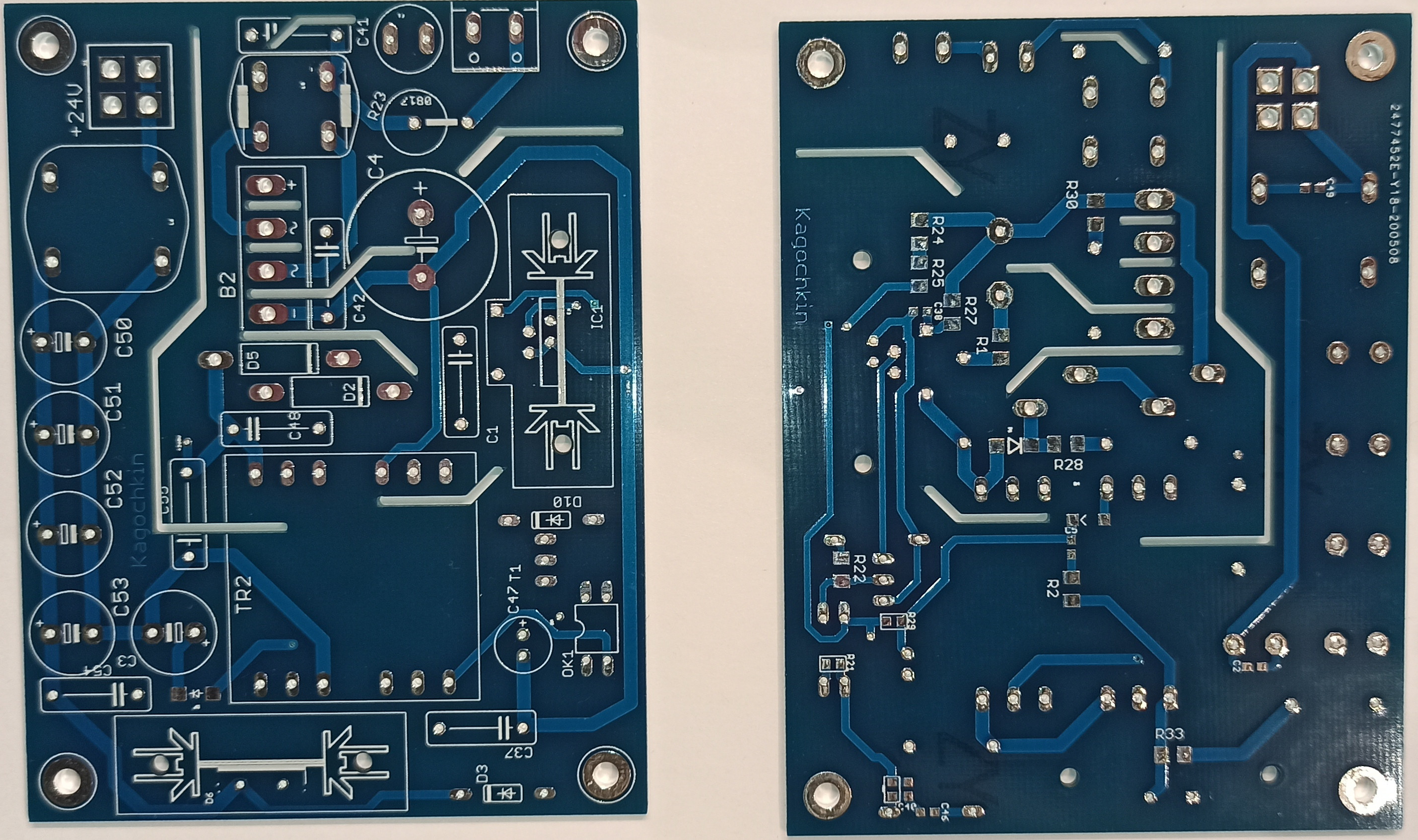
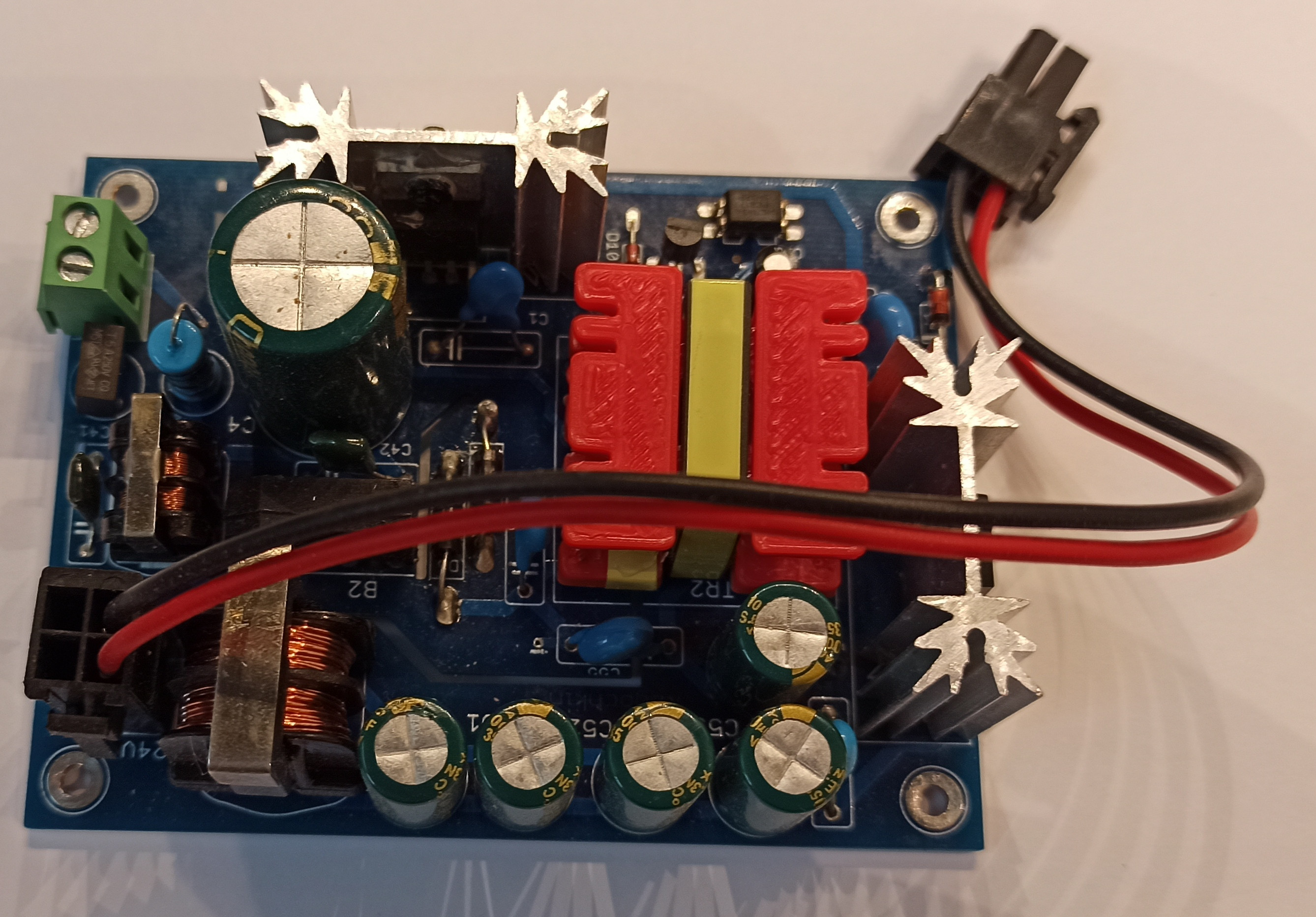 This is a classic Flyback converter on PKS607, which has shown itself very well and has been operating for over 1 year in 24/7 mode.
The schematic diagram can be taken here
This is a classic Flyback converter on PKS607, which has shown itself very well and has been operating for over 1 year in 24/7 mode.
The schematic diagram can be taken here
This is quite enough for a fully functional device, but if you want to assemble the front panel, then you need another board.

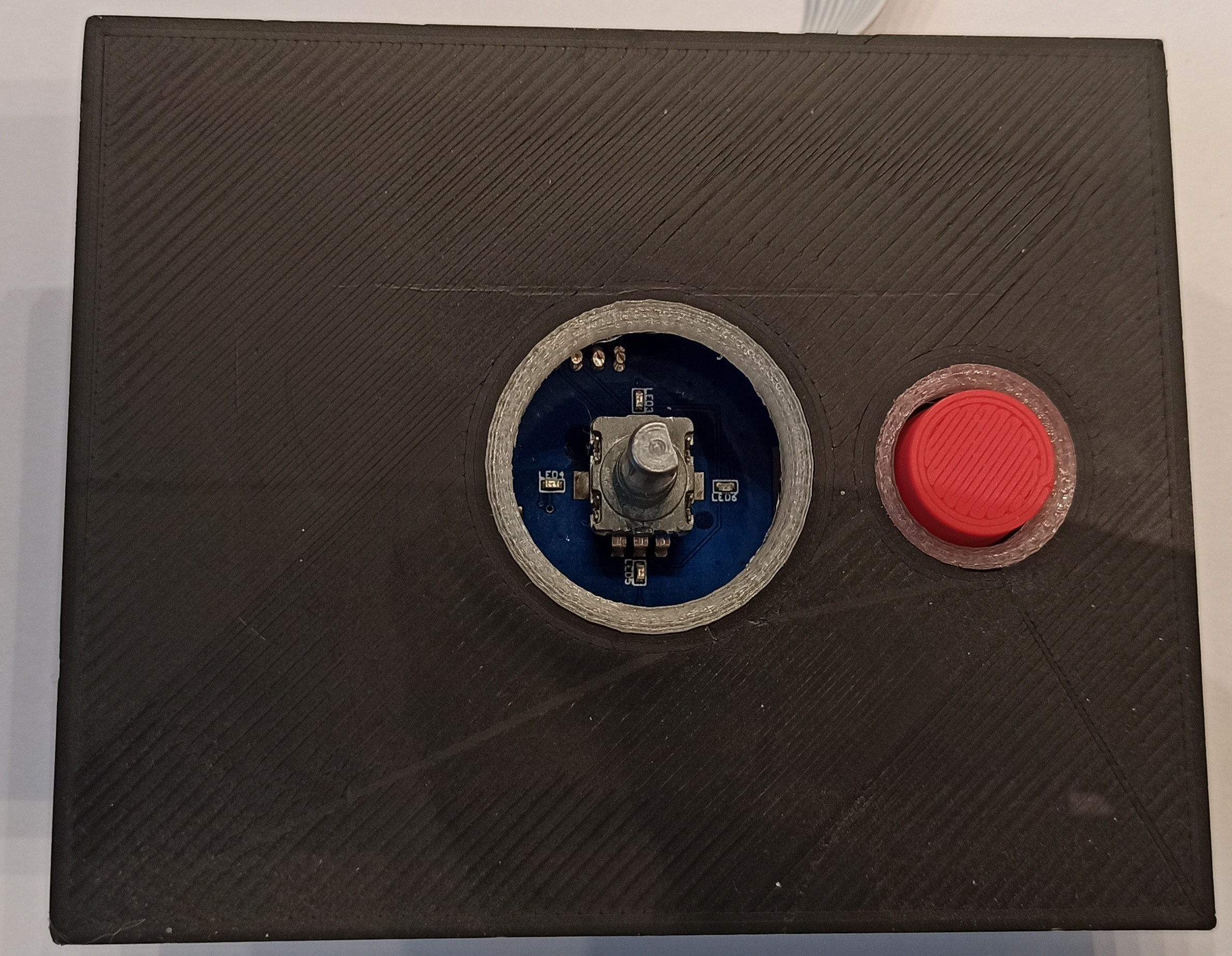
In general, without a control board, everything works quite well, but you need to turn off the device strictly through the WEB interface and only after a complete shutdown of the operating system - you can de-energize the entire system. This is due to the fact that the microcomputer will save all temporary files to the SD card and a power interruption at this moment will simply cause a violation of the file system and, as a result, impossibility to boot the system next time. In addition, it is convenient to place a volume control on the PC board and at least an on / off button. It may be convenient to have an infrared receiver for remote control from an IR remote control, which is sometimes much more convenient than turning on a cell phone or computer. And with the front panel the device will look quite professional. In my version, in the 9th version, I used the MCP1700 as a 3.3 V voltage source, which was not entirely justified, because in standby mode, the PSU on the second winding increased the voltage to 20 volts, which caused the breakdown of the MCP1700. So I just replaced it with a Zener diode for a nearest voltage. Next, I'll change the schematic. The circuit can be viewed here
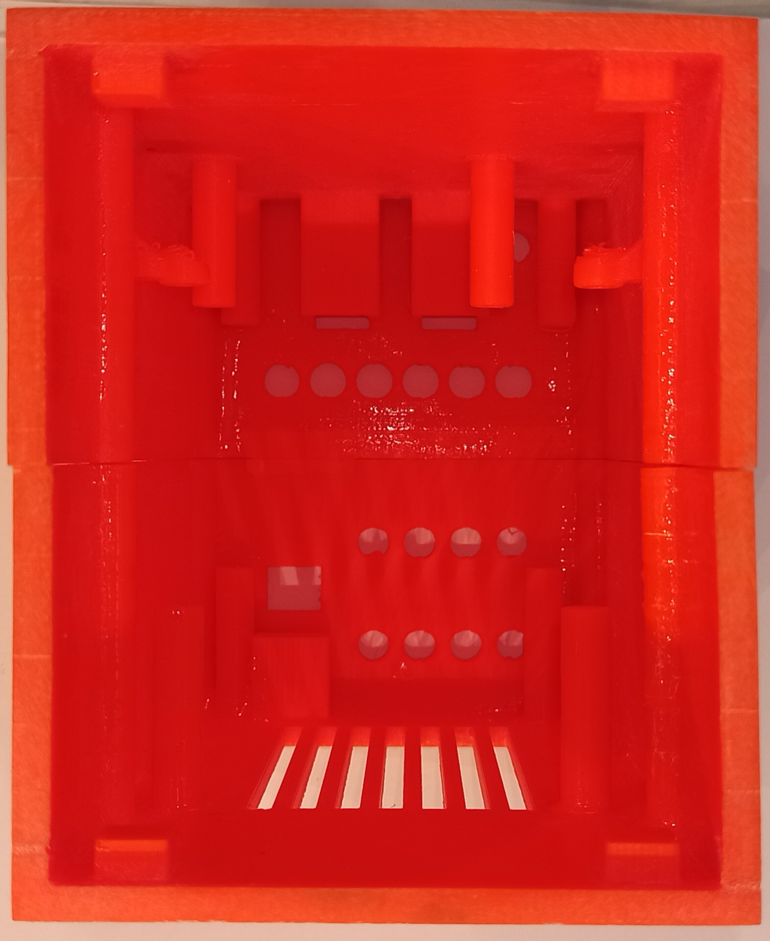
After soldering, everything needs to be inserted into the case 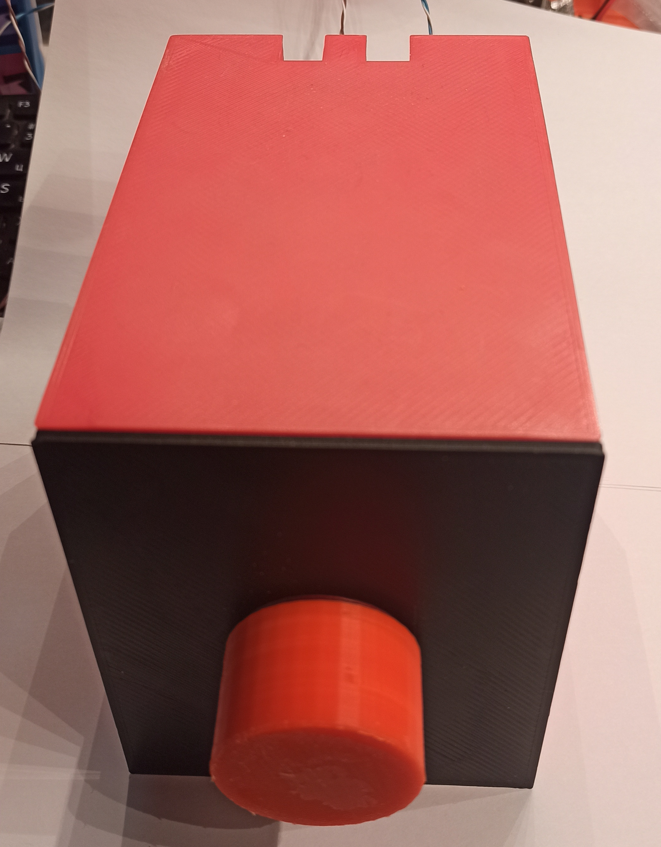 about the same or any other at your discretion.
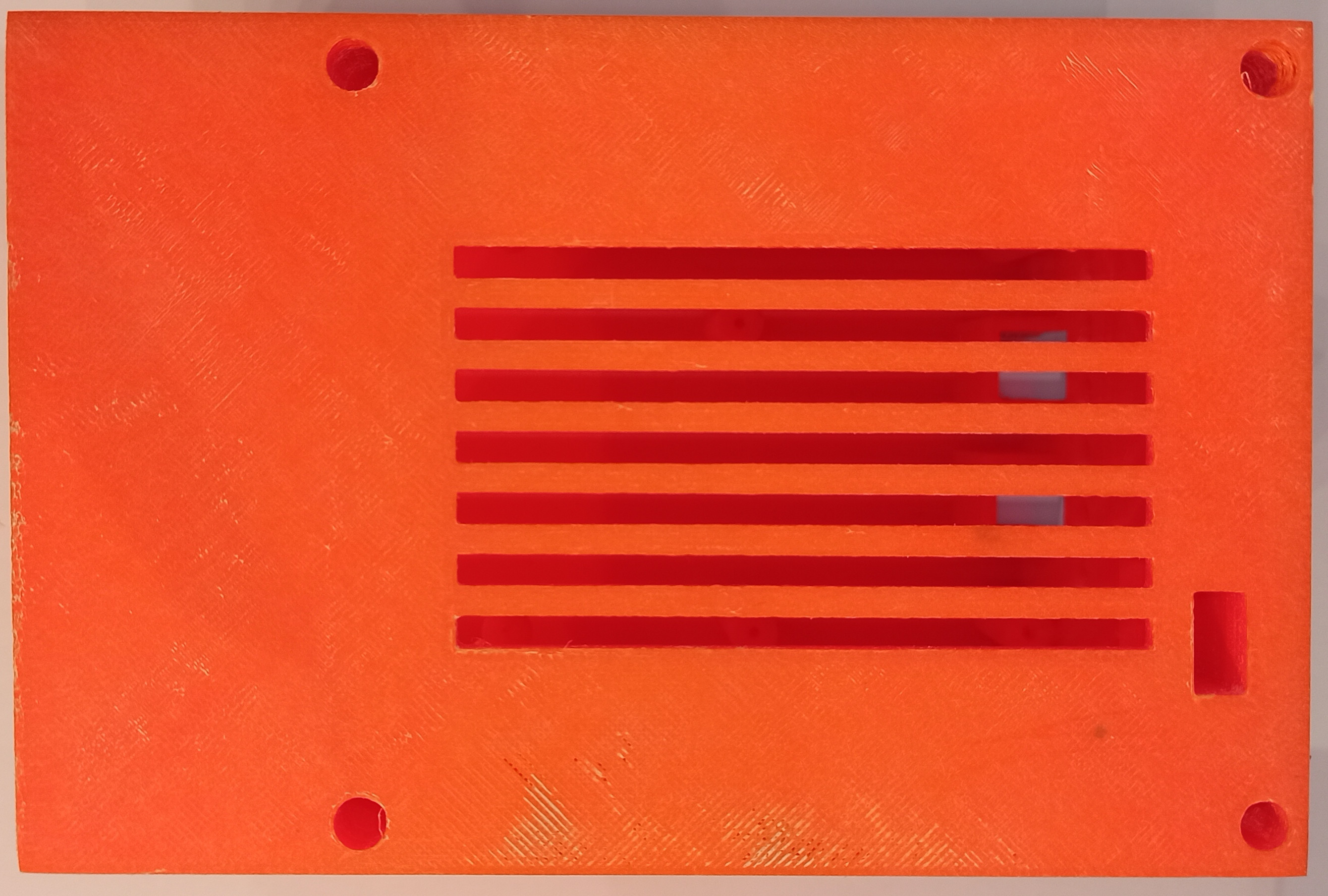
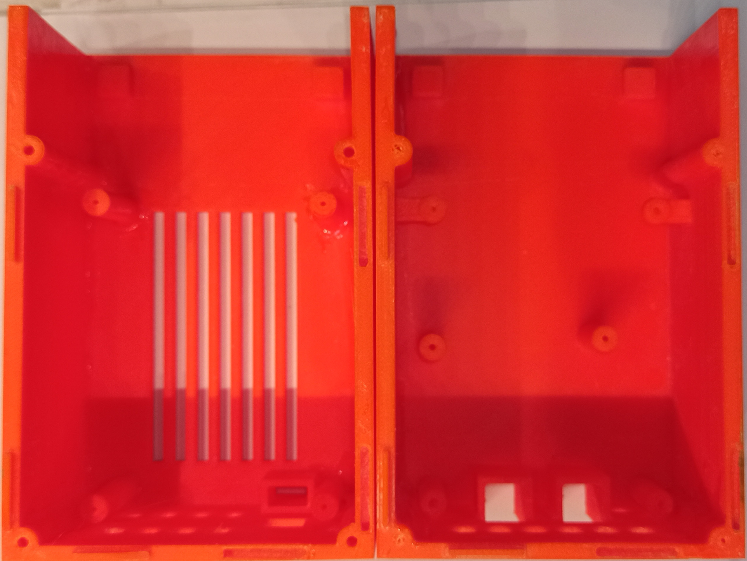
This enclosure 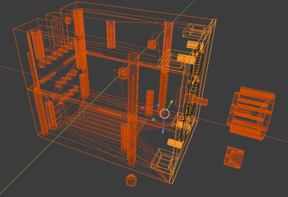 was designed and 3D printed.
 In fact, here everyone can choose an acceptable and desired way and perhaps the simplest solution is to install everything in one of the speakers enclosures, thereby simplifying the whole system.
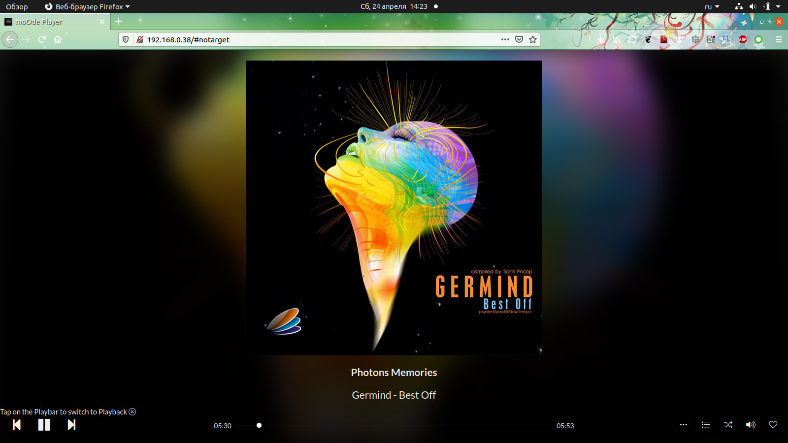
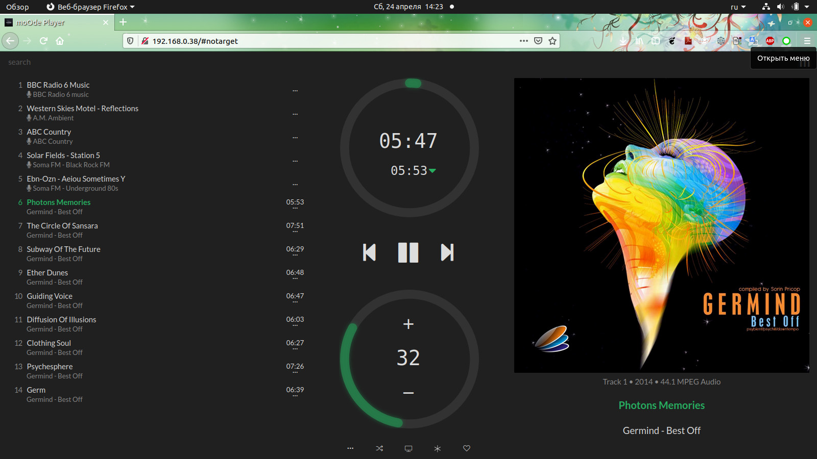
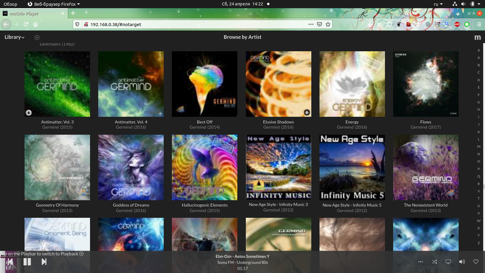
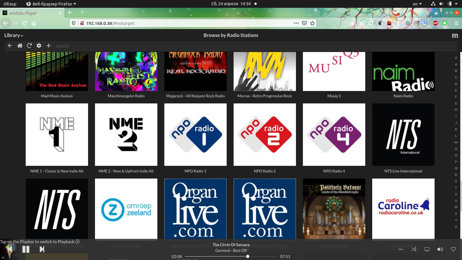
Now it remains to install and run the player itself with the WEB interface ...
I prefer moOde ™ audio player, this is a small Linux distribution with an integrated interface that works very well on RPI Zero W.
In the next articles I will tell you how to install and start the player and how to reduce its power consumption in standby mode.
In the meantime, you can read the second part - HIFI music center with Web control part 2
That's all for now, follow my publications on rmicro.ru and on Youtube.
Assembly part 1 Assembly part 2 Assembly part 3 Assembly part 4 Assembly part 5 Assembly part 6