Continuing the first part HIFI music center with Web control I'll tell you how to assemble a power supply. Earlier I said that the classic flyback converter from PowerInt PKS607 was taken as a basis, which showed itself very well and has been working for more than 1 year in 24/7 mode.
The circuit is interesting for its simplicity and sufficient power. The efficiency is approximately 82% at full load. The input voltage is 90-265 Volts (I have not tested it), the output voltage is 20-24 Volts at a current of 2 Amperes. With a long-term excess of the current of more than 2 Amperes, the protection is triggered, due to chip heating above 142 degrees. Re-inclusion is possible when the temperature decreases by 75 degrees. So for those who like to listen to music loudly, it is better to use the EE28 core and wind the secondary winding simultaneously with 4 wires with a diameter of 0.5 mm. I bought the microcircuits from the Chinese and in my case I had to use the resistor R27 to increase the voltage of internal zenner on the BP leg at the start of the microcircuit to 6.3 volts. If you have an original microcircuit, I would like to read the comments on how it starts up in this case. (with or without resistor R27)
For those wishing to repeat, I will give a scheem 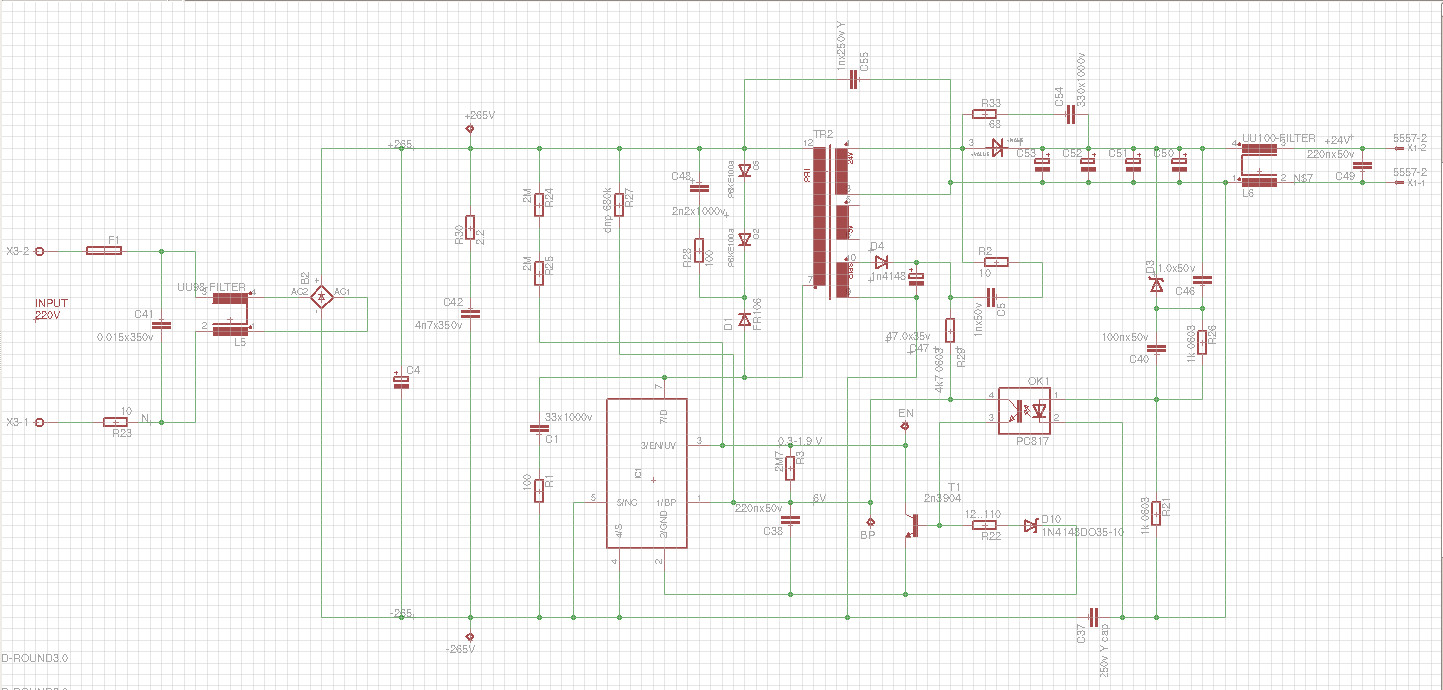 Although it practically does not differ from the typical one in the official documentation. Perhaps someone will have difficulties with winding the transformer, I will explain a little that my core is EE25 with a gap of about 0.1 mm, which is obtained by laying a fluoroplastic transformer adhesive tape between the halves of the core so that the inductance of the primary winding is 160-170 μH. First, we wind half of the primary winding - 16 turns 2x0.35mm, then the secondary 8 turns 2x0.5mm, then the auxiliary 5 turns 2x0.3mm and on top half of the primary 17 turns 2x0.35mm. All windings are strictly in one direction.
I had the EE25 core in stock
Although it practically does not differ from the typical one in the official documentation. Perhaps someone will have difficulties with winding the transformer, I will explain a little that my core is EE25 with a gap of about 0.1 mm, which is obtained by laying a fluoroplastic transformer adhesive tape between the halves of the core so that the inductance of the primary winding is 160-170 μH. First, we wind half of the primary winding - 16 turns 2x0.35mm, then the secondary 8 turns 2x0.5mm, then the auxiliary 5 turns 2x0.3mm and on top half of the primary 17 turns 2x0.35mm. All windings are strictly in one direction.
I had the EE25 core in stock 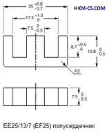 But the bobin had to be printed on a 3D printer
 ![]()
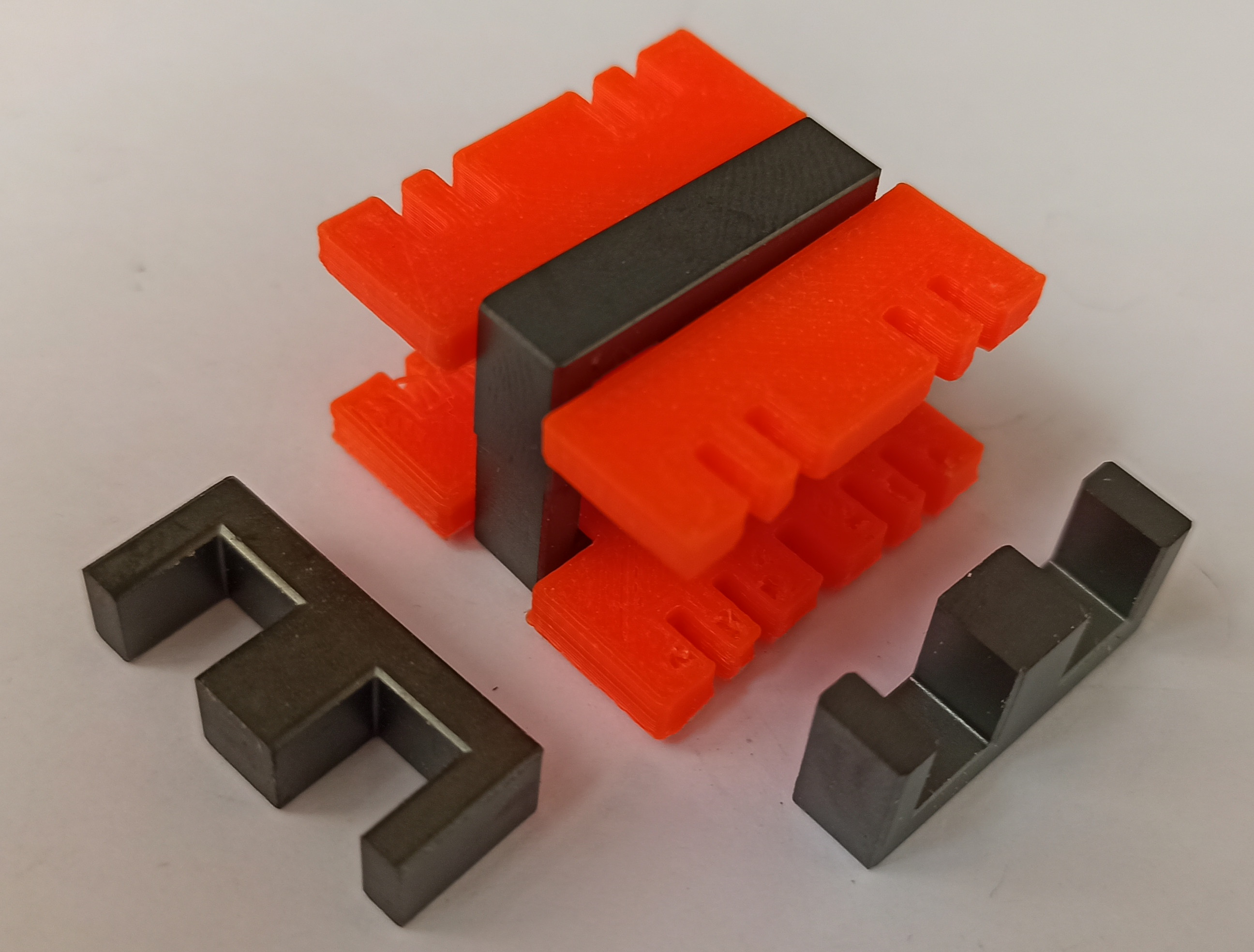
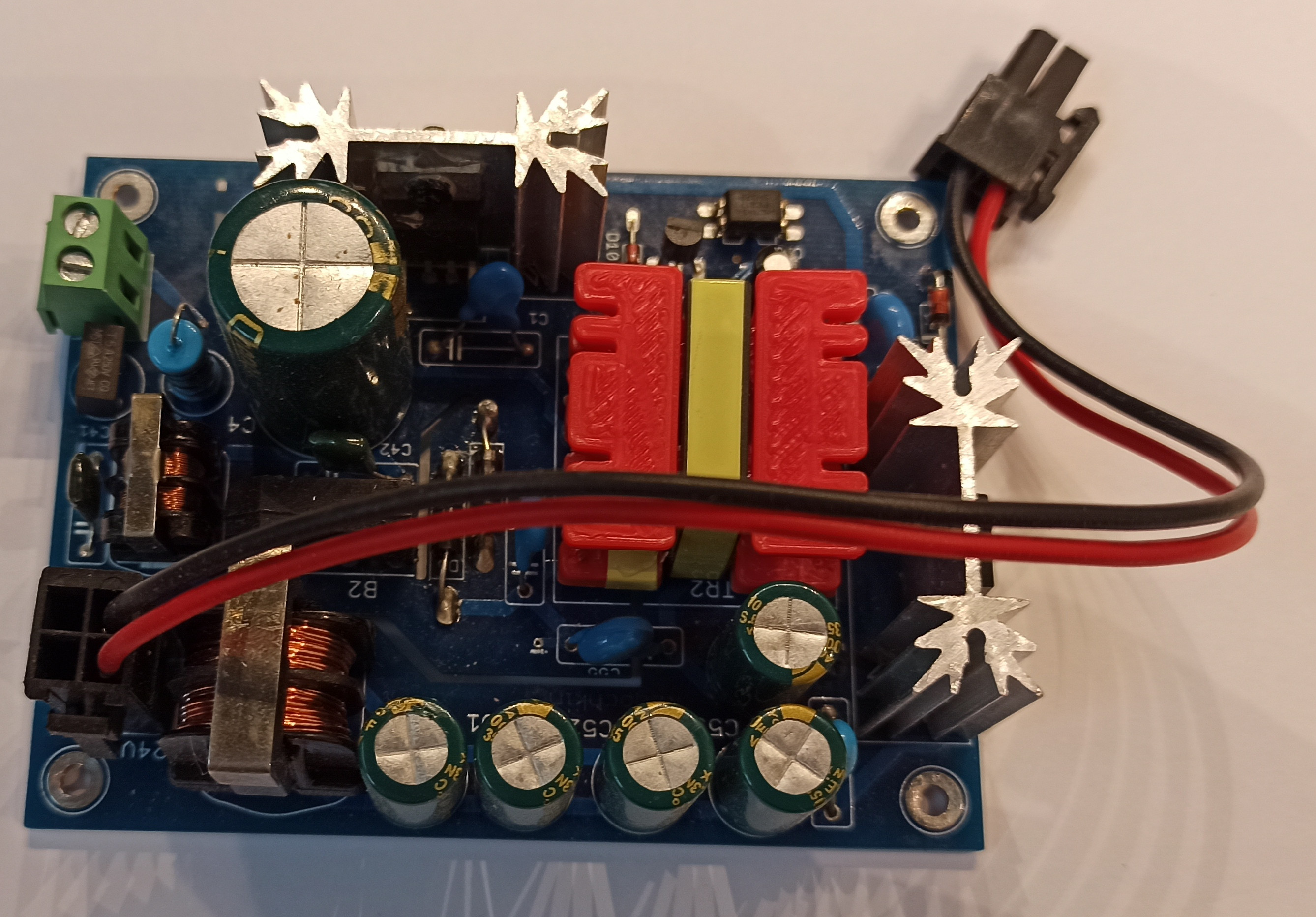
As legs, I used the remnants of the terminals of radio components.
All this "miracle" is placed on a 2-sided PCB 1.6mm, which is inserted into a plastic case, as in video
List of used components here
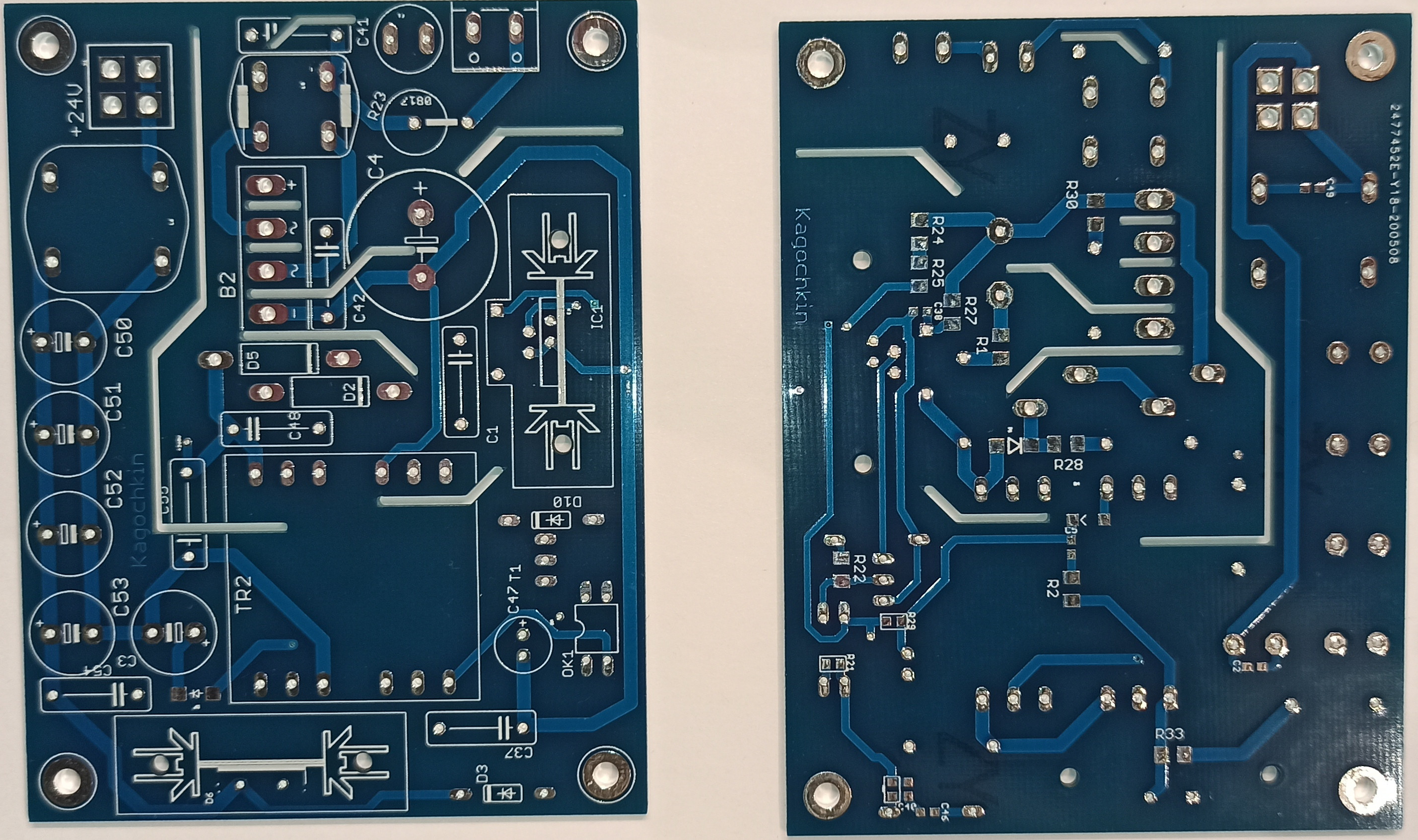
The printed circuit board looks like this 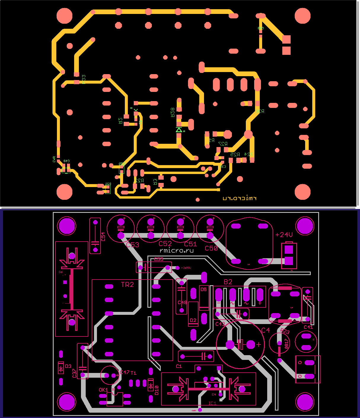 .
.
If there is a desire to repeat, I will give the Gerber files rmicro-PSU-5713-106
Attention, the circuit is powered by an alternating voltage of 220 volts! I recommend using increased safety measures to avoid electric shock!
That's all for now, follow my publications on rmicro.ru and on Youtube.
Assembly part 1 Assembly part 2 Assembly part 3 Assembly part 4 Assembly part 5 Assembly part 6